

A brief look at the operating principle
A residual current value describes only the installation section covered by the sensor. Monitoring of main distribution, subpanels and final circuits is planned together with the measurement objective and suitable sensor technology.
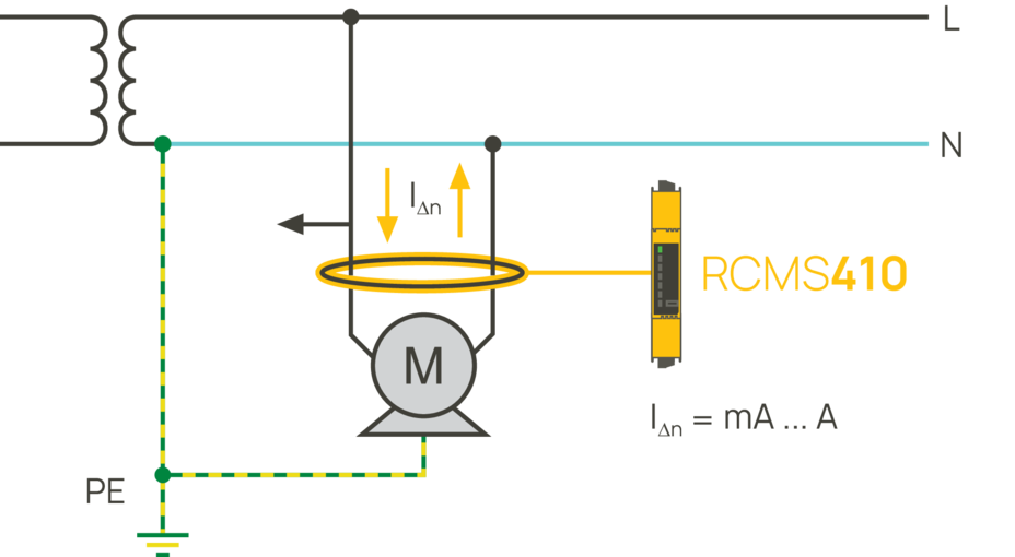
First define the question the measurement must answer
Designing residual current monitoring involves more than counting devices. The aim may be to track overall electrical condition, assess a particular production line or find a faulty final circuit. These questions may not be answered equally clearly from the same measuring point. Bender emphasises understanding the installation section covered by each sensor and the technology used. This allows measured values to be interpreted without drawing excessively broad conclusions about the whole installation.
Main boards and final circuits provide different detail
Main distribution measurements combine the effects of several loads. In large, complex installations, a change in a small final circuit may be difficult to distinguish. Moving measuring points closer to subpanels and final circuits can make the affected section easier to identify. Conversely, monitoring only final circuits may not fully describe the installation's overall condition. The information required from main distribution, the central earthing point, subdistribution and final circuits must be assessed together.
Sensor selection and data assessment complement one another
The measuring range must suit the smallest change to be detected. Where smooth DC components or high-frequency currents are expected, the sensor's ability to detect them must also be checked. Solutions such as RCMS150, RCMB300 or split-core RCMB330 can address different installation needs in final circuits. Model selection must be checked alongside conductor arrangement and communication requirements. Changes in alarm values over time and the operating state of loads may be more informative than a single instantaneous reading. Sound assessment combines device data with the installation's actual configuration and operating information.
Bender monitoring models by distribution level
Main distribution, subpanels and final circuits require different levels of detail. Compare channel configuration and sensor arrangements according to the measurement objective.
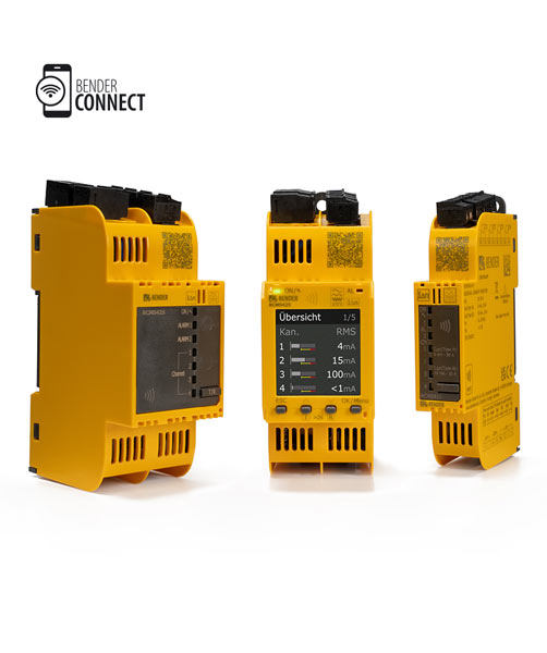
LINETRAXX® SmartDetect RCMS
Four channels and external sensor options support assessment of separate circuits or installation sections. Each channel has independently adjustable prewarning and main alarm thresholds.
Select measuring point, sensor aperture and current characteristic together. Type B/B+ requires a suitable sensor and function module B.Explore the model and documents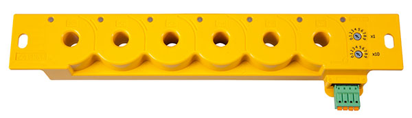
LINETRAXX® RCMS150 series
AC/DC-sensitive RCMS150 monitors residual current in final circuits across six separate channels, with separate RMS and DC evaluation per channel.
Check the monitored circuit's load and voltage limits in the technical data. RCMS150 uses BMS communication, while RCMS150-01 uses Modbus RTU.Explore the model and documents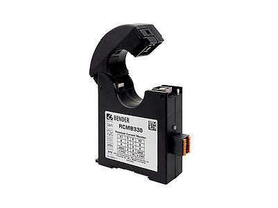
LINETRAXX® RCMB330
The integrated split-core current transformer allows sensor installation without mechanically disconnecting the existing conductor. The module monitors AC/DC residual current and sends prewarning and alarm information via Modbus RTU.
Check sensor aperture, measuring range and expected frequency components. A split-core design simplifies mechanical installation; installation conditions are defined in manufacturer documents.Explore the model and documentsInterpret the combined effect covered by the main measurement alongside the detail from final-circuit measurements. These models provide continuous monitoring; they do not automatically perform the duties of required protective devices. Product images belong to Bender.
Bender sources for these models
Bender technical explanations
This English summary is based on the Bender technical sources listed below.
- Bender — Measurement with a strategy (15 October 2026) ↗
- Bender — Residual current monitoring from the main distribution board to the final circuit ↗
Sources checked: 2026-10-19. Diagrams belong to Bender; explanations were summarised by ADEO Teknik and are presented here in English.