

A brief look at the operating principle
An IT system has its live conductors isolated from earth, or one system point connected to earth through a sufficiently high impedance. Early notification of the first insulation fault gives the maintenance team time to support operational continuity.
IT, TN-S, TT and HRG/LRG: see the difference in the connections
Start with how the source and equipment enclosures connect to earth. Then compare the monitored quantity and Bender products for that function.
Five earthing arrangements, different monitoring functions
On narrow screens, scroll the table horizontally. Select a system name to jump to its diagram and products.
| System | Source earthing | Enclosure connection | Monitored quantity / method | First-fault approach |
|---|---|---|---|---|
| IT ↓ | Isolated; alternatively one point through sufficiently high impedance | Earthed through protective conductors | IMD: insulation resistance. Compatible EDS: faulty-circuit location. | Subject to design conditions, the first fault can be signalled without immediate disconnection. Automatic-disconnection conditions apply to a second fault on another live conductor. |
| TN-S ↓ | Source point directly earthed | PE connection to the earthed source point | RCM/RCMS: residual-current monitoring; required protection is provided separately. | The faulty circuit is disconnected by suitable protection when its operating conditions are met. |
| TT ↓ | Source point with its own earth electrode | Installation electrode independent of the source electrode | RCM/RCMS: residual-current monitoring; it does not replace RCD protection. | Earthing and protection must jointly satisfy the disconnection conditions. |
| HRG ↓ | High-resistance NGR between neutral and earth | Protective earthing retained | NGRM: NGR resistance, neutral-to-earth voltage and current. | Alarm or tripping depends on the application and protection plan; uninterrupted operation after the first fault is not guaranteed. |
| LRG ↓ | Low-resistance NGR between neutral and earth | Protective earthing retained | LRG-rated NGRM: NGR resistance, neutral-to-earth voltage and current. | Earth-fault alarm/tripping follows the selected protection arrangement. Do not assume IT-style first-fault tolerance. |
IT system
Live conductors are isolated from earth, or one source point is earthed through a sufficiently high impedance. Equipment enclosures retain protective earthing.
IMD: insulation resistance. Compatible EDS: faulty-circuit location.
Subject to design conditions, the first fault can be signalled without immediate disconnection. Automatic-disconnection conditions apply to a second fault on another live conductor.
The dashed Z* path represents the alternative connection through a sufficiently high impedance. There is no direct source-to-earth bond; enclosure PE remains connected.
Bender model examples for this function
An IMD monitors system insulation resistance; compatible fault-location components help identify the faulty outgoing circuit.
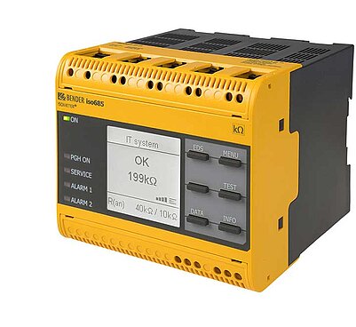
ISOMETER® iso685-…-P
Continuously monitors IT system insulation resistance and signals values below the response threshold. Its integrated locating current injector supports fault location with a compatible EDS44x system.
Select the P variant and compatible EDS/current-transformer combination for fault location; do not assume the standard iso685 has the same injector function.Explore the model and technical documents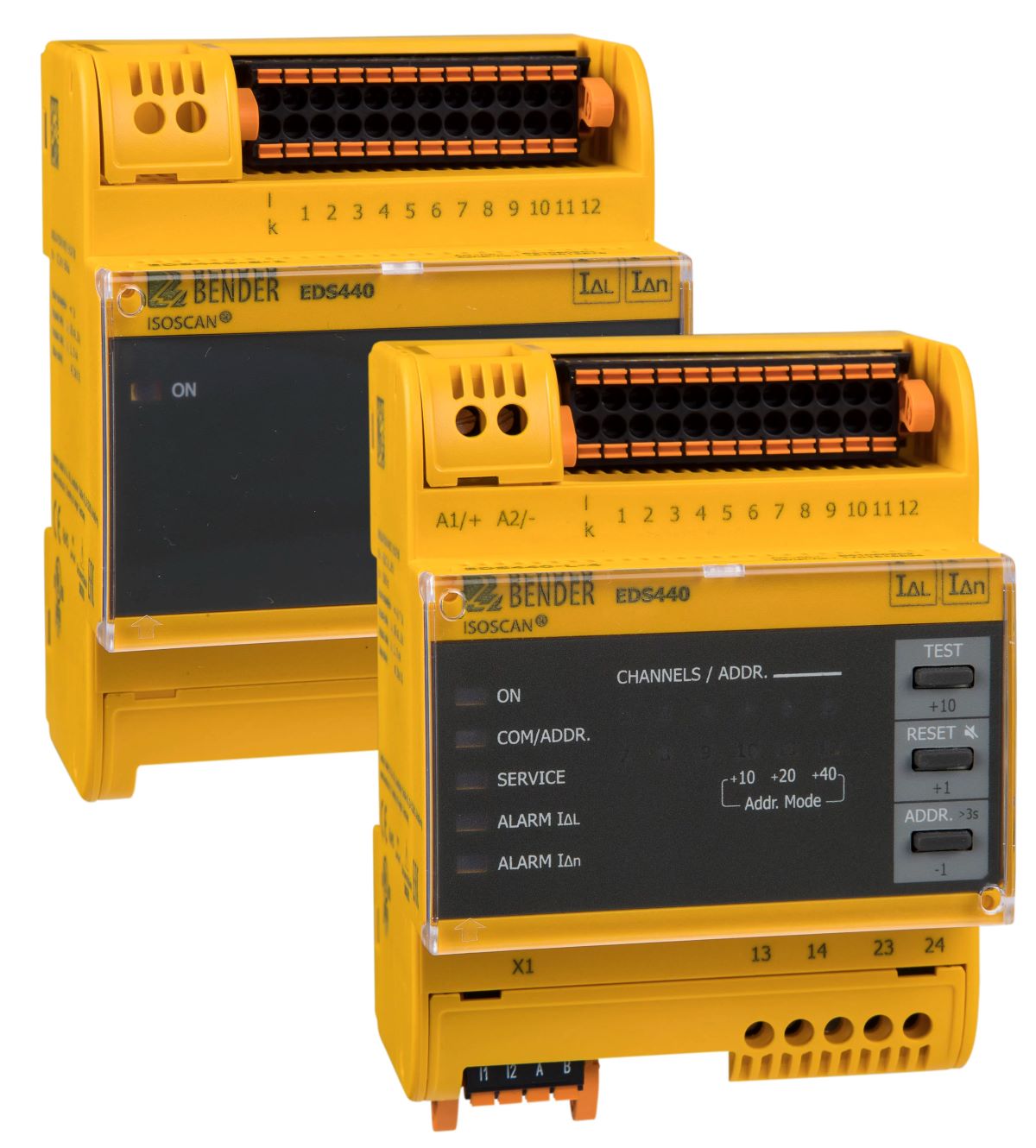
ISOSCAN® EDS440
Evaluates locating-current signals from iso685-D-P or a compatible PGH injector through measuring current transformers. Channel information identifies the outgoing circuit containing the insulation fault.
It is not an IMD or locating current source on its own. Select the injector, channel-to-feeder mapping and suitable measuring current transformers together.Explore the model and technical documentsTN-S system
The source point is directly earthed. Enclosures connect to that point through PE; N and PE remain separate conductors.
RCM/RCMS: residual-current monitoring; required protection is provided separately.
The faulty circuit is disconnected by suitable protection when its operating conditions are met.
N and PE remain separate after the defined source point. No additional N–PE bridge is drawn at the load.
The TN-S example concerns a suitable measuring section with separate N and PE. Do not transfer the standard residual-current measurement example to a TN-C section in which PEN combines neutral and protective functions.
Bender model examples for this function
Residual current is monitored in a suitable section with separate N and PE; the central system brings together measured values and alarms from connected devices.
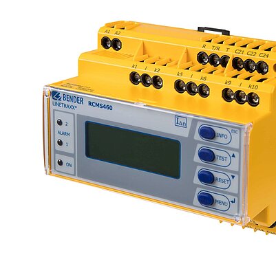
LINETRAXX® RCMS460-D
Monitors outgoing circuits in an earthed distribution system on separate channels using compatible measuring current transformers. Select the appropriate sensor per channel for AC, pulsating DC or smooth DC components.
This example concerns a TN-S measuring point; do not generalise the standard differential arrangement to a TN-C section. Monitoring/alarm does not replace required RCD protection.Explore the model and technical documents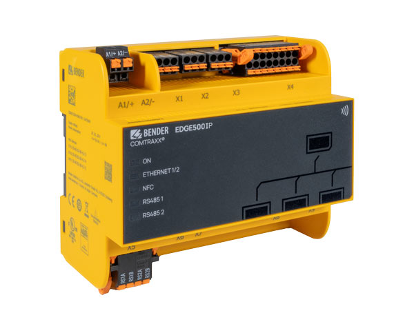
COMTRAXX® EDGE500IP
Collects measured values and status information from connected Bender and compatible third-party devices in a central web interface. It supports alarm management, logging and supervisory integration; it does not directly measure residual current.
Measurement is performed by the RCMS and its transformers. Verify BMS/BCOM/Modbus connections, device compatibility and required function licences for the selected system.Explore the model and technical documentsTT system
The source point is directly earthed. Installation enclosures connect through PE to a local electrode independent of the source electrode.
RCM/RCMS: residual-current monitoring; it does not replace RCD protection.
Earthing and protection must jointly satisfy the disconnection conditions.
The source electrode and the local electrode for installation enclosures are separate. N is not bonded to PE at the load.
The ground band places the two separate electrodes in the same soil; it is not a metallic PE bridge. Soil is not shown as electrical insulation.
Bender model examples for this function
In a TT system, residual current monitoring and protective disconnection are different duties. The following models illustrate this distinction.
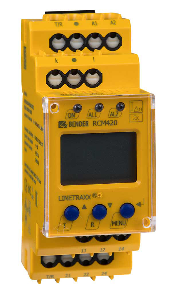
LINETRAXX® RCM420
Monitors AC and pulsating DC residual currents in a TT system using a suitable external measuring current transformer. Provides prewarning and alarm information.
Do not interpret Type A measurement as smooth DC detection. RCM420 is a monitoring device and does not replace the protective arrangement required for the TT system.Explore the model and technical documents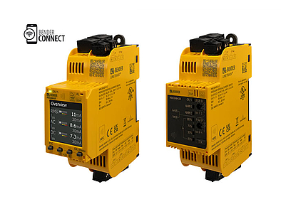
LINETRAXX® SmartDetect MRCDB425
As an AC/DC-sensitive MRCD, evaluates residual current in a suitable TT circuit. Protection is completed with a compatible measuring current transformer and the external circuit breaker specified by the manufacturer.
Requires the CTUB102-CTBC… combination and a circuit breaker with undervoltage release meeting the manufacturer’s disconnection conditions; do not present the device alone as a load-disconnecting RCD.Explore the model and technical documentsHRG · High resistance grounding
The source neutral is connected to earth through the NGR. Enclosures remain connected to PE; the NGR limits earth-fault current.
NGRM: NGR resistance, neutral-to-earth voltage and current.
Alarm or tripping depends on the application and protection plan; uninterrupted operation after the first fault is not guaranteed.
The NGR sits between source neutral and earth, not in the enclosure PE conductor. This HRG example does not distribute N to the load.
Bender model examples for this function
The NGR limits earth fault current; the NGRM monitors resistor condition and related current/voltage quantities. The models are alternative examples.
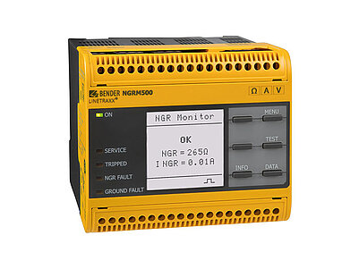
LINETRAXX® NGRM500
Monitors neutral grounding resistor condition, current through it and neutral-to-earth voltage in an HRG system. Uses active/passive measurement methods for NGR monitoring.
Specified for HRG applications. Select NGR rated values, CD coupling device, current transformer and alarm/tripping arrangement together.Explore the model and technical documents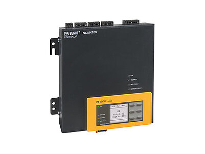
LINETRAXX® NGRM700
Monitors NGR resistance and the associated neutral current/voltage in an HRG system. A detachable HMI and communication functions support local indication and data transfer to supervisory systems.
The HRG model has a different intended scope from NGRM750, which is specified for LRG. Select active measurement, coupling device and sensor using the manufacturer documentation.Explore the model and technical documentsLRG · Low resistance grounding
The neutral is earthed through a low-resistance NGR. Protective earthing is retained; the monitor is selected for LRG applications.
LRG-rated NGRM: NGR resistance, neutral-to-earth voltage and current.
Earth-fault alarm/tripping follows the selected protection arrangement. Do not assume IT-style first-fault tolerance.
LRG retains the neutral–NGR–earth principle; select the resistor and monitor for the low-resistance grounding application scope.
Bender model examples for this function
For NGR monitoring in an LRG system, select a model specified for low-resistance grounding. These devices are not automatically interchangeable with HRG models.
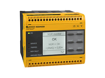
LINETRAXX® NGRM550
Monitors NGR condition and associated current/voltage in low-resistance-grounded transformer and generator systems. Supports evaluation of an open NGR connection and earth fault indications.
Use its LRG application scope; selection differs from the HRG NGRM500. Coupling, transformer ratio and alarm/tripping settings depend on installation conditions.Explore the model and technical documents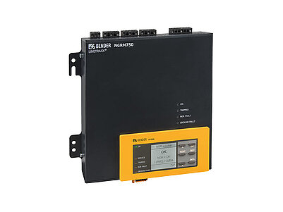
LINETRAXX® NGRM750
Monitors NGR condition, neutral current and voltage in an LRG system. Its detachable HMI supports panel-door indication and central monitoring through communication interfaces.
Do not treat the LRG model as equivalent to NGRM700, which is specified for HRG. Verify phase-voltage and other additional functions against connection and option requirements.Explore the model and technical documentsThese are product examples illustrating the network and function; they do not exclude other documented applications of a model or constitute a complete installation design or mandatory product set.
The diagrams are conceptual ADEO Teknik drawings based on Bender technical references; product images belong to Bender. Detailed measurement and protection connections follow the actual system and manufacturer documentation.
Technical references for the diagrams and product documents
- Bender — Power supply systems ↗
- Bender — IT systems as reflected in the standards ↗
- Bender — Residual current monitoring in earthed systems ↗
- Bender — High resistance grounding ↗
- ISOMETER® iso685-…-P ↗
- ISOSCAN® EDS440 ↗
- LINETRAXX® RCMS460-D ↗
- COMTRAXX® EDGE500IP ↗
- LINETRAXX® RCM420 ↗
- LINETRAXX® SmartDetect MRCDB425 ↗
- LINETRAXX® NGRM500 ↗
- LINETRAXX® NGRM700 ↗
- LINETRAXX® NGRM550 ↗
- LINETRAXX® NGRM750 ↗
What does the earthing arrangement change?
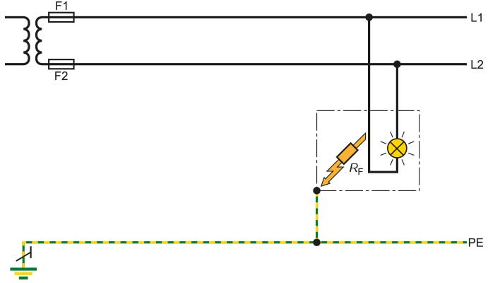
In a TN system, one source point is directly earthed and the exposed conductive parts of the installation are connected to that point by protective conductors. In a TT system, one source point is directly earthed, while exposed conductive parts use earth electrodes electrically independent of the source earth electrode. In an IT system, live conductors are isolated from earth or one system point is connected to earth through a sufficiently high impedance. “Unearthed IT” does not remove protective earthing: exposed conductive parts are earthed individually, in groups or collectively through protective conductors.
Why does the first insulation fault matter?
The first fault current in an IT system depends on the system's insulation resistance and leakage capacitance to earth. Under suitable design conditions, the first fault can be indicated without immediately disconnecting the supply. A Bender ISOMETER insulation monitoring device tracks the condition of the electrically connected system and alerts the operating team when resistance falls below the configured alarm level. The first fault should be investigated and cleared before a second insulation fault occurs on a different live conductor. The conditions for automatic disconnection after the second fault must be met by the protective and exposed-conductive-part earthing arrangements.
What do IMD and EDS provide together?
The IMD reports the overall insulation condition; it does not always identify the faulty outgoing circuit by itself. A system with a compatible locating current injector, EDS evaluator and current transformers can narrow the search to the relevant circuit. Fixed or portable fault location supports maintenance planning. In healthcare, industry, marine and energy applications, system configuration is assessed alongside loads, system size and operating requirements. Continued operation after the first fault is not an unconditional guarantee of safety or uninterrupted supply for every IT installation.
Select the product function for the actual earthing arrangement
The possibility of earthing one point through a high impedance in the IT definition does not make any IMD suitable for every HRG or LRG system. In HRG systems, NGRM monitoring of the neutral grounding resistor and ground faults differs from locating the faulty outgoing circuit with suitable RCMS solutions. Verify the monitoring method and product compatibility against the actual earthing arrangement and manufacturer documentation.
- In an IT system, a suitable IMD monitors insulation resistance; EDS helps identify the faulty circuit using a compatible locating current source and sensors.
- In a suitable TN-S/TT arrangement, RCM/RCMS monitors residual current. An RCD or suitable MRCD arrangement provides protection; the residual current value is not a direct insulation resistance measurement.
- For resistance-earthed systems, NGRM selection follows the HRG/LRG application scope. A device’s supply voltage or ability to detect AC/DC earth fault components does not establish suitability for every type of system.
Bender technical explanations
This English summary is based on the Bender technical sources listed below.
- Bender — IT system: Unearthed systems for maximum availability ↗
- Bender — Why the IT system is often the best choice (technical article) ↗
- Bender — Types of distribution systems for power supply ↗
- Bender — IT systems as reflected in the standards ↗
- Bender — Electrical safety for high resistance grounded systems ↗
Sources checked: 2026-10-25. Bender diagrams and ADEO Teknik summaries; additional comparison diagrams are credited separately.