

A brief look at the operating principle
The neutral conductor N and protective conductor PE serve different purposes. Unwanted connections can divert operating current through earthing and equipotential bonding paths; suitable measuring points make this visible.
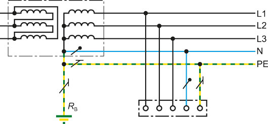
The difference between TN-S, TN-C-S and TT
During normal operation, N may carry returning load current, while PE forms part of the protective connection. In TN-S systems, these functions use separate conductors. In TN-C systems, neutral and protective functions are combined in a PEN conductor; in TN-C-S systems, they are combined in one part and separated in the next. Once N and PE have been separated, an additional N–PE bridge must not be created. In a TN-C section where PEN combines neutral and protective functions, the ordinary residual-current measurement arrangement based on separate N and PE is not applicable; assess the measuring point in the suitable TN-S section. In TT systems, one point of the supply source is earthed; exposed conductive parts of the installation are connected to an earth electrode arrangement independent of the source's system earth.
What can an unwanted N–PE connection cause?
Additional N–PE connections in the TN-S section can create parallel return paths for part of the neutral current. Current may flow through equipotential bonding, conductive building structures or data cable screens. These stray currents can be associated with electromagnetic compatibility problems and corrosion. Bender emphasises checking connections, particularly in existing installations undergoing conversion or extension. Protective earthing connections and an incorrectly reconnected neutral are different situations; the single-line diagram and actual connections must be assessed together.
How is the central earthing point monitored?
In a suitable TN-S arrangement, a sensor at the central earthing point helps monitor changes in current along this path. Bender describes significant mains-frequency current in the PE path as an indication worth investigating for unwanted multiple connections. However, a measurement alone does not locate an N–PE connection conclusively; physical leakage paths and operating conditions must also be examined. Measurements at the main distribution board, central point and outgoing circuits can complement one another. This monitoring does not automatically replace the required protective devices or expert verification of connections. Measurement history can also help establish when changes appeared after new loads were connected or maintenance was performed.
| Arrangement | Relationship between N and PE | Points to examine |
|---|---|---|
| TN-S | N and PE are separate conductors | Unwanted additional N–PE connections and parallel current paths |
| TN-C-S | PEN in one section, followed by separate N and PE | Consistent connections downstream of the separation point |
| TT | Exposed conductive parts are connected to an earth electrode independent of the system earth | Compatibility of protection and measurement arrangements with the actual TT system |
Bender models for TN-S / TT monitoring
Select the measuring point and suitable sensor together to monitor residual and stray currents in arrangements with separate N and PE.
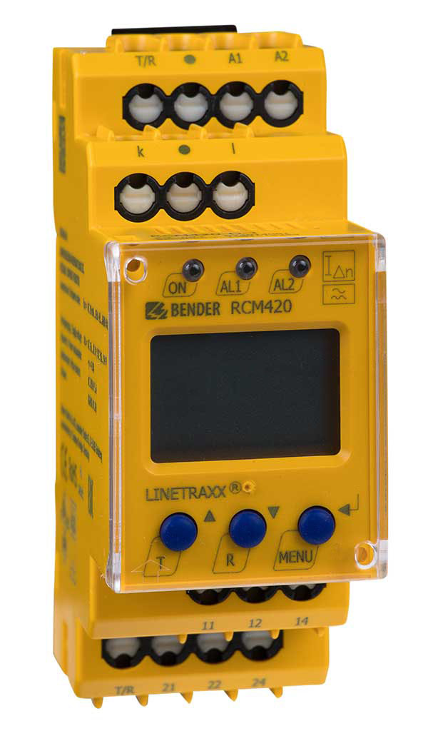
LINETRAXX® RCM420
Provides Type A residual current monitoring in TN and TT systems. With a suitable measuring arrangement, it can also monitor currents in the PE conductor or N–PE connection.
Sensitive to AC and pulsating DC; not selected for smooth DC detection. A compatible external sensor such as CTAC is required.Explore the model and documents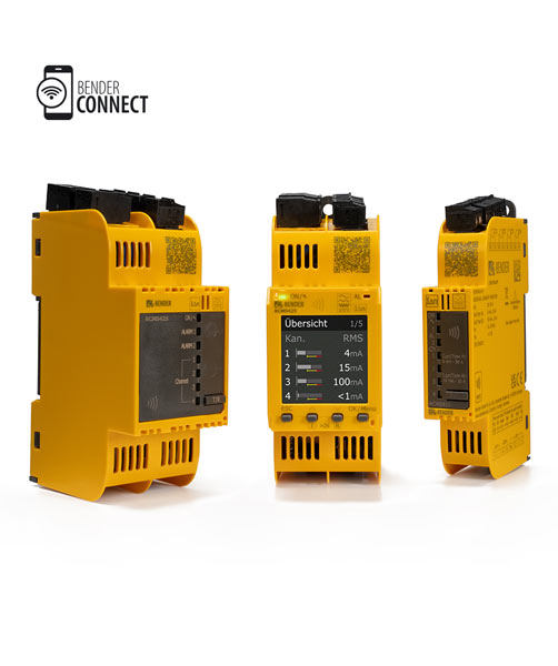
LINETRAXX® SmartDetect RCMS
Monitors current in different installation sections over four separate channels. Bender lists stray current and additional N–PE connection monitoring in TN-S systems among its applications.
AC/DC-sensitive Type B/B+ measurement requires a suitable CTUB sensor and function module B. Measurement alone does not conclusively locate an incorrect connection.Explore the model and documentsAssess the N–PE connection arrangement alongside the actual distribution system in the monitored section; RCM monitoring does not replace required protection. Product images belong to Bender.
Bender sources for these models
Bender technical explanations
This English summary is based on the Bender technical sources listed below.
- Bender — Central earthing point (CEP) ↗
- Bender — Types of distribution systems for power supply ↗
- Bender — Permanent residual current monitoring in TN-S systems ↗
Sources checked: 2026-10-22. Diagrams belong to Bender; Turkish explanations summarised by ADEO Teknik.