

A brief look at the operating principle
Identical system voltages do not mean the same IMD will suit two applications. Assess system leakage capacitance, connected converters and the measuring method together, and match them to the selected model's technical capabilities.
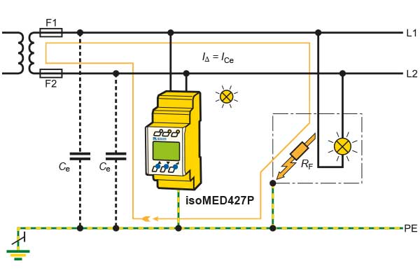
Ce is a property of the system configuration
System leakage capacitance Ce describes the capacitive effect of live conductors and connected components relative to earth. The cables and EMC filters of a large installation contribute to this value. Bender notes that wide physical distribution and interference suppression measures can produce high Ce, particularly in PV installations. This quantity is expressed in microfarads; it is different from insulation resistance, which is measured in ohms. High Ce alone does not indicate a resistive insulation fault, but it affects assessment of the measuring method and the device's application scope.
The measuring method must suit the connected equipment
Bender's technical explanation discusses superimposed DC measuring voltage, AMP and AMP Plus as separate methods. Rectifiers and inverters galvanically connected to an AC system, along with changing frequencies, matter when selecting a method. AMP Plus is one option for these conditions and high system leakage capacitances; it should not be assumed that all Bender IMDs use the same method. For example, the iso685 offers AMP Plus alongside other profile-dependent methods. Selection must follow the measuring profiles and application conditions specified for the model, rather than the family name alone.
Compare voltage, Ce and response conditions together
An IMD's nominal system voltage, auxiliary supply and permissible system leakage capacitance are separate technical quantities. For example, Bender specifies automatic capacitance adaptation up to 25 µF for the iso415R; this limit cannot be applied to other series. Response time must also be read in conjunction with the Ce and fault resistance conditions stated in the document. The selected variant's AC/DC voltage range, any required coupling device and the connected equipment must be considered together. As Bender's distributor in Türkiye, ADEO Teknik helps compare these values against current model documents.
Bender IMD examples by system leakage capacitance
Compact control circuits, main circuits with power electronics and large PV installations have different measuring conditions. These models provide contrasting examples for comparing Ce and application scope together.
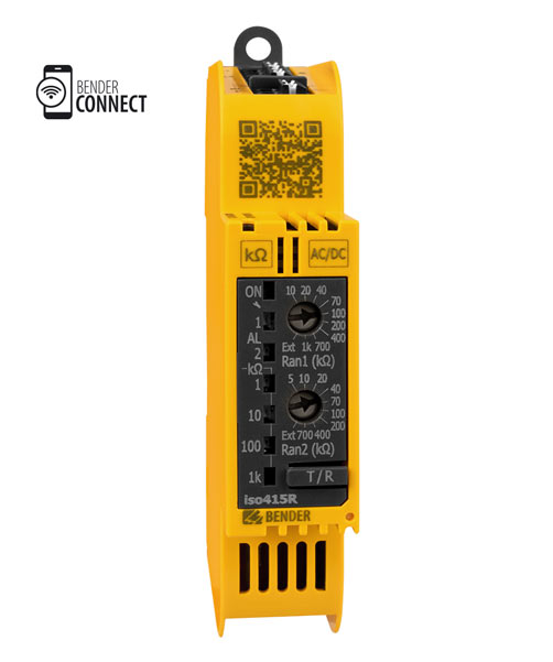
ISOMETER® iso415R
Monitors insulation resistance in unearthed AC/DC circuits and automatically adapts to system leakage capacitance up to 25 µF.
Small main-circuit applications are assessed against the manufacturer's conditions for systems without VFDs and variant-dependent voltage ranges.Explore the model and documents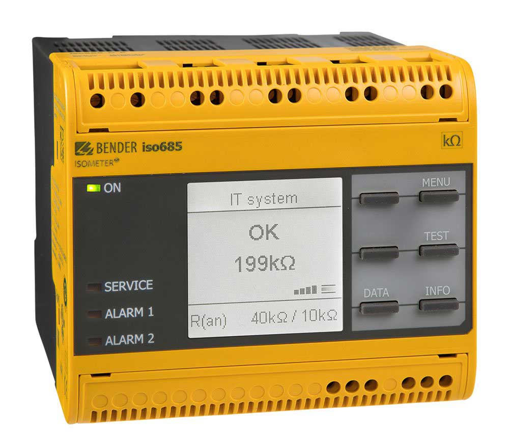
ISOMETER® iso685…
Monitors IT systems using AMP Plus and other profile-dependent methods, automatically adapting to the existing system leakage capacitance.
In systems containing rectifiers or inverters, select the measuring profile, voltage and device variant together.Explore the model and documents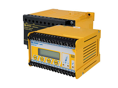
ISOMETER® isoPV with AGH-PV
Offers adaptation to system leakage capacitance up to 2000 µF and a PV-specific measuring method for PV main circuits configured as IT systems.
isoPV is used only with the AGH-PV coupling device; voltage and Ce limits apply to this product combination.Explore the model and documentsThe Ce limit is a different quantity from alarm threshold or response time. Product images belong to Bender.
Bender sources for these models
Bender technical explanations
This English summary is based on the Bender technical sources listed below.
- Bender — Insulation monitoring: The concept / Measurement methods ↗
- Bender — ISOMETER isoPV with AGH-PV: Leakage capacitance and EMC ↗
- Bender — ISOMETER iso685: Measurement profiles and system voltage ↗
- Bender — ISOMETER iso415R: Capacitance range and response conditions ↗
- Bender — IT system: Earth capacitance principle illustration ↗
Sources checked: 2026-10-19. Diagrams belong to Bender; explanations were summarised by ADEO Teknik and are presented here in English.