

A brief look at the operating principle
Correct residual current measurement starts with a suitable sensor and all live conductors of the monitored circuit passing through the same measuring window. Compatibility with the connected RCM or EDS evaluator is as important as the sensor aperture.
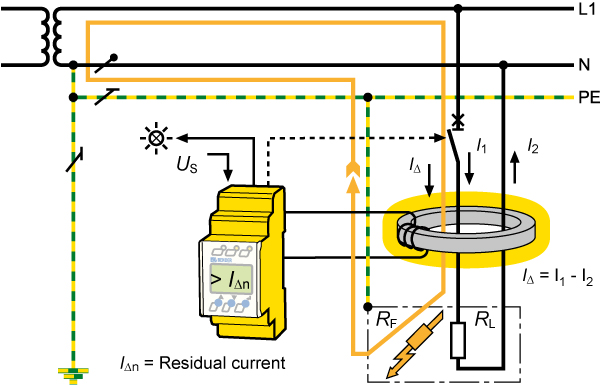
Measurement evaluates the circuit's outgoing and returning currents together
In the RCM principle, all live conductors of the monitored circuit pass through the same measuring current transformer window, including the neutral where present. The protective conductor PE remains outside the measuring loop. In the ideal case with no leakage or fault current, the sum of the currents in the live conductors is zero; current returning via PE or other paths creates a difference in the measurement. Leaving a live conductor outside the measurement can cause normal load current to be interpreted as residual current. Defining which circuit a sensor covers is therefore a fundamental panel design decision.
Consider the aperture, conductor arrangement and load conditions together
The internal aperture is selected to suit the monitored circuit's conductor bundle and the panel layout. Conductor arrangement, available space and the sensor's mounting conditions must be considered together using the product document; simply choosing a large aperture does not guarantee correct measurement. Load and inrush currents also matter in sensor selection. For example, certain P cores in the CTUB100 family feature integrated magnetic shielding for high load and inrush currents. This feature is not present in every sensor and must be checked when comparing models and variants.
Do not assume RCM and EDS use the same sensor
A sensor that fits mechanically is not necessarily electrically compatible with the selected evaluator. The sensor and evaluator form a measurement chain. The AC/DC waveform to be detected, sensor electronics, supply and signal connections must be specified together. Bender defines different evaluator combinations for CTUB101 and CTUB102 modules. Within the CTAC family, certain /01 variants are reserved for specific EDS devices. EDS evaluates the test current generated for insulation fault location; an EDS sensor therefore does not automatically replace a general RCM sensor. The exact combination must be checked against the manufacturer's compatibility table.
Bender sensors in the measurement chain
Compatibility with the connected evaluator is as important as the measuring window and conductor arrangement.
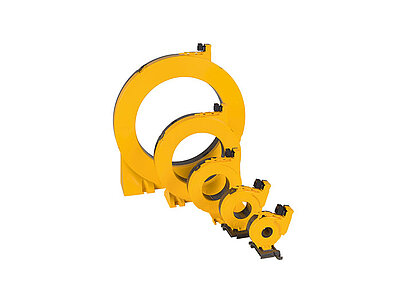
LINETRAXX® CTAC series
CTAC is a family of current transformers that generates measuring signals for compatible RCM/RCMS devices. Compare internal diameters against the monitored conductor bundle.
Standard CTAC and /01 variants have different compatibility. CTAC20/01 and CTAC35/01 are listed for EDS441/461/491; standard CTAC models are used for RCM420.Explore the model and documents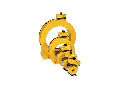
LINETRAXX® CTUB100 series
Combining a CTBC core and CTUB electronic module, the series provides a suitable evaluator with measuring signals for AC and DC currents. P cores offer integrated magnetic shielding.
CTUB101 is listed with RCMA420/423 and CTUB102 with RCMS410/425/460/490. Supplies and exact model combinations differ; CTUB variants are not all interchangeable.Explore the model and documentsThese sensors alone are neither alarm evaluators nor protective circuit breakers. Live conductor and PE arrangements follow the measuring method and device documents. Product images belong to Bender.
Bender sources for these models
Bender technical explanations
This English summary is based on the Bender technical sources listed below.
- Bender — How does residual current monitoring work? ↗
- Bender — LINETRAXX CTUB100: Evaluator combinations and magnetic shielding ↗
- Bender — LINETRAXX CTAC: RCM/RCMS and EDS variant compatibility ↗
Sources checked: 2026-10-22. Diagrams belong to Bender; Turkish explanations summarised by ADEO Teknik.