

A brief look at the operating principle
The residual current waveform is a key input when choosing the sensor and evaluator. Detecting AC and pulsating DC is different from detecting smooth DC; frequency coverage must also be checked for each model.
Fault current waveforms: Type A and Type B
Type A and Type B describe the current waveforms a device can detect. The key difference is the smooth DC component, which Type B also covers. The diagrams below show how fault current changes over time.
Sinusoidal AC
The current periodically changes direction; the signal crosses to both sides of the zero line.
Pulsating DC
The current remains in one direction; its value changes in pulses and, in this example, falls to zero between them.
Smooth DC
The current flows in one direction and, in this example, has a constant value. Smooth DC detection is covered by Type B.
| Fault current waveform | Type A* | Type B* |
|---|---|---|
| Sinusoidal AC | Covered | Covered |
| Pulsating DC | Covered | Covered |
| Smooth DC | Not suitable for smooth DC | Covered |
* This comparison applies within the declared measuring and frequency range of the device and sensor. Type B does not imply identical sensitivity at all frequencies.
This distinction explains detection coverage. The monitoring/alarm function of an RCM and the protective function of an MRCD/RCD must be assessed separately.
The diagrams are schematic current-versus-time representations of the waveforms.
Bender's technical explanation of Type A / Type B ↗Bender model examples for Type A and Type B
After identifying the expected fault current waveform, explore the model suited to the monitoring or protection task. The detail pages for these examples contain technical specifications, variants and manufacturer documents.
For AC and pulsating DC
Two different tasks: monitoring/alarm and modular protection.
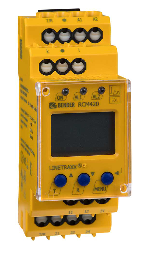
LINETRAXX® RCM420
Monitors sinusoidal AC and pulsating DC residual currents in TN and TT systems, providing prewarning and alarm.
Used with the compatible external measuring current transformer specified by the manufacturer.Explore the model and documents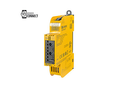
LINETRAXX® SmartDetect MRCD410R
AC- and pulsating-DC-sensitive modular residual current device. Forms a protection arrangement with a compatible current transformer and circuit breaker.
Assessed together with a compatible CTAC measuring current transformer and a circuit breaker with an undervoltage release.Explore the model and documentsDetection that also covers smooth DC
Monitoring or modular protection in circuits where smooth DC components may occur.
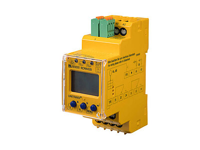
LINETRAXX® RCMA420
Type B device that monitors AC, pulsating DC and smooth DC residual currents in TN and TT systems. Provides measurement and alarm information.
Used with a compatible CTUB101–CTBC measuring current transformer combination.Explore the model and documents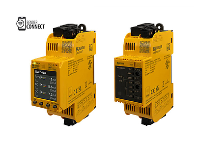
LINETRAXX® SmartDetect MRCDB425
AC/DC-sensitive modular residual current device. Selectable Type B / B+ characteristic; used with a compatible sensor and circuit breaker.
Assessed together with a compatible CTUB102–CTBC measuring current transformer and a circuit breaker with an undervoltage release.Explore the model and documentsType A / Type B defines detection coverage. An RCM provides monitoring and alarms; the protective function of an MRCD must be assessed with the sensor and circuit breaker combination specified by the manufacturer. Frequency range, thresholds and settings must be checked for each model. Images belong to Bender.
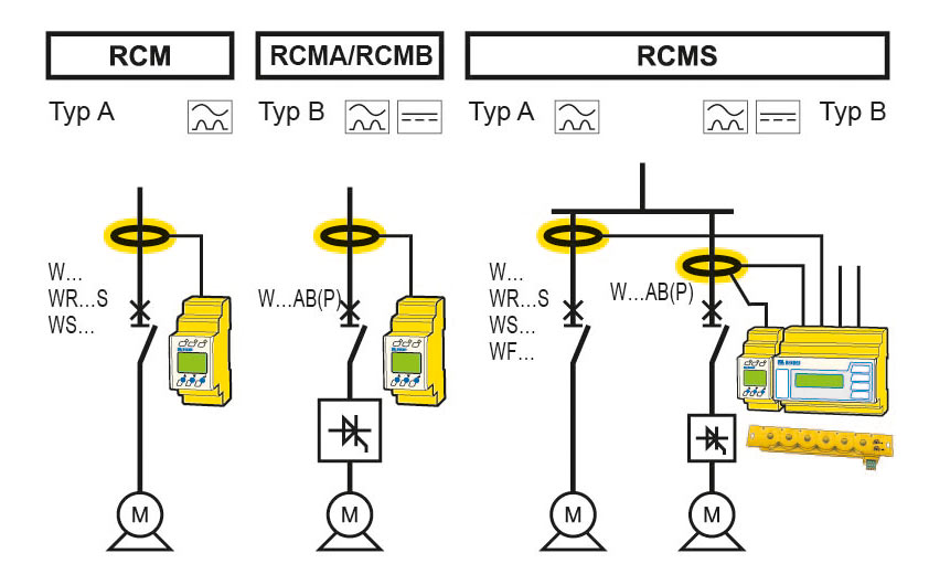
Start with the expected fault current waveform
Residual current in a circuit should not be assumed to consist solely of sinusoidal AC. Loads with rectifiers or drives may produce pulsating DC, smooth DC and different frequency components. Type A monitoring covers AC and pulsating DC fault currents; detecting smooth DC requires a different capability. AC/DC-sensitive solutions designated Type B also cover smooth DC components. Selection therefore starts with the expected current waveform and the operational information required, rather than the load name alone.
The type designation does not define the entire frequency range
The term ‘Type B’ does not mean that all devices have the same frequency coverage, measuring range or sensitivity. Review the frequency coverage and adjustable frequency response on the manufacturer's current product page. For example, AC/DC-sensitive measurement in the SmartDetect RCMS family requires function module B together with a suitable Type B/B+ sensor series. This product detail prevents the assumption that every ordering variant in a family comes with identical hardware and licences. The configuration also determines which components are evaluated for analysis and alarms.
Select the sensor, supply and evaluator together
The physical diameter of a current transformer alone does not establish compatibility. In the Bender CTUB100 example, the sensor core and electronic module convert AC/DC current into an evaluable signal; the compatible evaluator and supply arrangement are specified separately for each module. The measuring range, waveform, wiring and required supply must therefore be checked together. Measurement channel locations and alarm thresholds are planned around the installation's purpose. Adding RCM condition monitoring does not automatically replace an RCD or other protective functions; monitoring and protection must be assessed separately.
| Selection question | Type A approach | Type B / AC-DC-sensitive approach |
|---|---|---|
| Which waveforms? | AC and pulsating DC | AC, pulsating DC and smooth DC |
| How is frequency coverage determined? | From the relevant model and sensor specifications | From the relevant model, sensor and settings |
| Is the device name alone enough? | Sensor compatibility must be checked separately | The sensor, module and ordering variant must be checked together |
Bender technical explanations
This English summary is based on the Bender technical sources listed below.
- Bender — How does residual current monitoring work? ↗
- Bender — LINETRAXX SmartDetect RCMS: frequency response and function modules ↗
- Bender — LINETRAXX CTUB100: sensor and evaluator compatibility ↗
- LINETRAXX® RCM420 · Manufacturer product information ↗
- LINETRAXX® SmartDetect MRCD410R · Manufacturer product information ↗
- LINETRAXX® RCMA420 · Manufacturer product information ↗
- LINETRAXX® SmartDetect MRCDB425 · Manufacturer product information ↗
Sources checked: 2026-10-19. The manufacturer's image belongs to Bender. Waveform diagrams were prepared for ADEO Teknik based on Bender's technical explanations.