Insulation Monitoring in Large-Scale PV Systems · IMD
BENDER APPLICATION INTRODUCTION · BRIEF SUMMARY
Turn a general alarm into faulty-string information in large PV installations
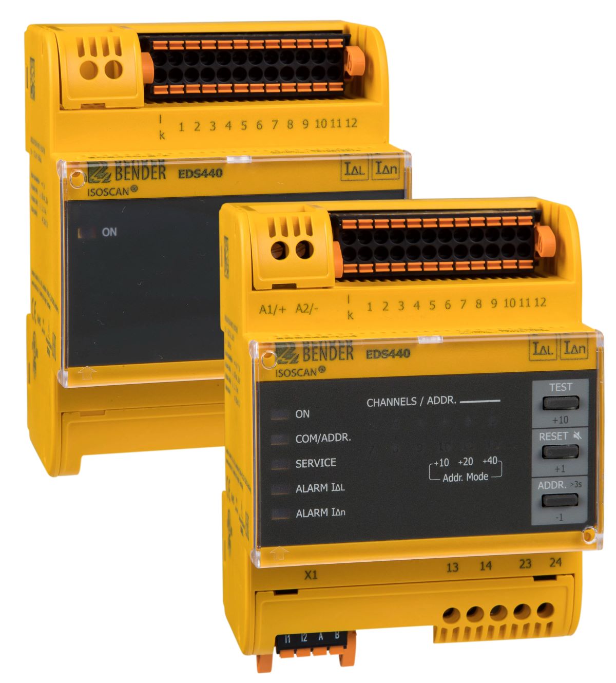
An insulation alarm in a large solar installation does not identify the faulty string by itself. In Bender’s PV brochure, ISOMETER monitors the system’s insulation level, while ISOSCAN/EDS and suitable measuring current transformers help locate the relevant circuit.
Moisture, contamination and ageing can change insulation levels across large PV installations. Continuous insulation monitoring and fault location to identify the relevant circuit provide different information.
BENDER DISTRIBUTOR IN TÜRKİYE · ADEO TEKNİK
isoPV1685DP and isoPV1685RTU in solar applications
Two main insulation monitoring options for large-scale PV systems. Consider system leakage capacitance, measurement requirements and variant selection together.
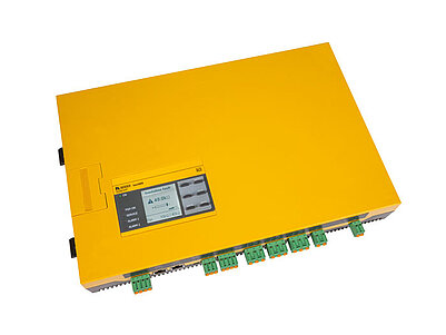
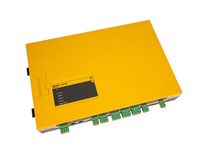
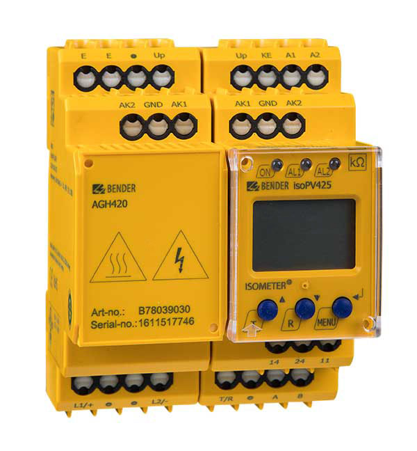
Insulation monitoring with a graphical display in large photovoltaic IT systems, with an integrated locating current injector to support EDS insulation fault location.
Insulation monitoring in large-scale PV IT systems. Compare the technical data of the isoPV1685RTU-425 variant with the isoPV1685P-425 option on the same product page.
BENDER DISTRIBUTOR IN TÜRKİYE · INTERACTIVE PV SYSTEM GUIDE
PV and storage at a common AC IT panel.
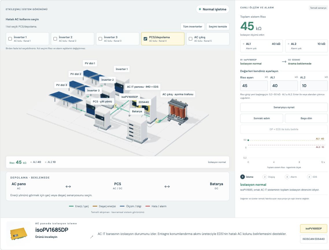
Three PV inverters and the storage system connect to a common unearthed AC IT busbar. The battery connects to the AC side through a bidirectional PCS. isoPV1685DP or isoPV1685RTU in the AC panel monitors overall insulation condition. Select charging or discharging and mark the AC branches on which to create simultaneous faults. Inverters 1, 2 and 3 can be selected individually or together; PCS/storage and the outgoing AC branch can also be added. Set Riso and the AL1/AL2 thresholds in the measurement panel. The entered resistance updates the alarm state immediately. Play the scenario or proceed step by step: follow the insulation resistance drop, isoPV1685 prewarning and alarm, and identification of the selected faulty AC branches on separate DP + EDS channels. Scenario progress is retained when changing energy mode or faulty branch selection. The two IMDs are shown as alternatives in the same position.
Charging and discharging · AC panel ↔ PCS ↔ battery
Initial state: PV inverters and the storage PCS are connected to a common AC IT panel. Select the energy direction and one or more AC branches on which to create a fault; play the scenario or use “Next step”. Set Riso and the AL1/AL2 thresholds in the measurement panel; the alarm state updates accordingly. During playback, follow the resistance drop and threshold crossings. After the DP + EDS search, all selected faulty AC branches are shown with their own channel numbers. Riso measurement pauses during EDS operation; the last measured value is retained. RTU has no integrated locating current injector.
Riso, alarm thresholds and EDS steps
Riso is the equivalent insulation resistance to earth of the monitored AC IT system; it is not a measurement of a single branch. Initially, AL1 = 40 kΩ and AL2 = 10 kΩ are selected. Riso and both thresholds can be changed within the example range of 0.2–50 kΩ; AL1 cannot be lower than AL2. This range belongs to the simulation.
Set the value: The entered Riso value is applied immediately. When a threshold changes, the same resistance value is evaluated against the new AL1/AL2 thresholds.
AL1 prewarning: A prewarning occurs when Riso falls below your AL1 threshold. A value equal to the threshold does not trigger an alarm in this example.
AL1 + AL2 alarm: Both alarms become active when Riso also falls below your AL2 threshold. The IMD alarm alone does not identify the faulty branch.
DP + EDS search: DP’s locating current is evaluated through measuring current transformers on the AC branches. Riso measurement pauses during this process; the displayed value is the last measurement.
Branch result: EDS identifies all selected faulty AC branches with separate channel results; the selected charging/discharging direction is retained.
The thresholds and resistance values belong only to this educational example; they are not factory settings or application recommendations. Playback moves from the entered initial value to an illustrative fault value below AL2; if the lower limit prevents reaching a value below AL2, no EDS result is generated. Changing a value or threshold pauses the scenario and applies the new starting condition; energy direction and multiple branch selection are retained. Branch selection does not automatically change the overall system Riso; individual branch resistances are not calculated. When all branches are deselected, the general IMD alarm continues to depend on the entered Riso, while the EDS search and channel results close. The accelerated steps do not represent actual device response times. Multiple results are summarised together in this example; in a real system, locating current division between faulty branches and channel conditions can affect detection. EDS does not measure insulation resistance per branch. With RTU selected, the sequence ends at the general insulation alarm; EDS fault location in this example requires DP.
isoPV1685DP · Monitoring in the AC panel
The IMD with graphical display in the AC panel monitors the insulation condition of the AC IT busbar. Its integrated locating current injector supports insulation fault location with EDS; insulation resistance measurement pauses temporarily during fault location.
Monitors the AC IT busbar from the same AC panel position as an alternative to DP. RTU has no integrated locating current injector; in this example, EDS fault location is available only when DP is selected.
The EDS in the AC panel evaluates the measuring current transformer on each PV inverter’s separate AC branch before it joins the common AC busbar. PV inverters 1, 2 and 3 are monitored on separate EDS channels; together with PCS/storage and the AC outgoing branch, all five AC branches can be selected simultaneously. EDS identifies each faulty branch through its own measuring current transformer and channel result. With charging or discharging selected, follow the Riso drop and the IMD’s AL1/AL2 alarm, followed by the DP + EDS search and the identification of the selected faulty AC branches on separate channels, all in the same view. Energy direction and insulation fault location are shown as separate layers. This does not represent DC string identification behind an inverter or battery cell fault location.
The storage branch joins the common panel through the bidirectional PCS’s AC connection. The battery is on the PCS’s DC side. During charging, energy flows from the AC panel to the PCS, which feeds the battery through AC/DC conversion. During discharging, energy flows from the battery to the PCS, which supplies the AC panel and outgoing AC branch through DC/AC conversion. PV generation is not shown during discharge. The measuring current transformer is shown on the AC side of the storage branch.
As Bender’s distributor in Türkiye, ADEO Teknik provides technical product information and quotation support for selecting IMDs, EDS devices and compatible measuring current transformers.
Turn a general alarm into faulty-string information in large PV installations
An insulation alarm in a large solar installation does not identify the faulty string by itself. In Bender’s PV brochure, ISOMETER monitors the system’s insulation level, while ISOSCAN/EDS and suitable measuring current transformers help locate the relevant circuit.
Define the monitoring point according to the inverter’s galvanic configuration.
System voltage, leakage capacitance and fault location requirements determine the product combination in large PV circuits.
02 · SOLUTION APPROACH
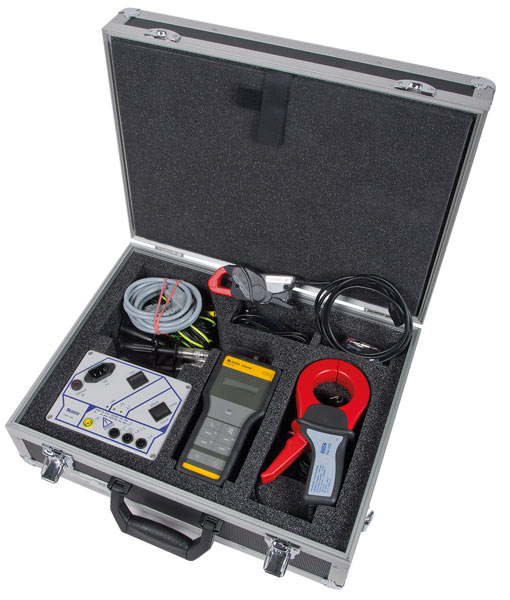
Match fixed-transformer or portable fault finding approaches to the site arrangement.
After choosing a product family for the application, compare the model’s measurement scope, accessory compatibility and communication options on its detail page.
The explanation, Bender’s relevant sector publication and official application page form the basis of this content. The image is presented in its original form from the source brochure.
Product families fulfil different measurement and notification duties. The model’s full scope and required components are identified in the relevant technical source.
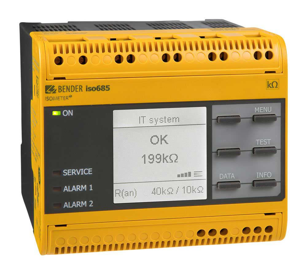
Insulation monitoring devices for large photovoltaic IT systems up to DC 1500 V, with RTU communication or an integrated locating current injector depending on the variant.
No products match your search. Shorten the model name or clear the filters.
OTHER OPTIONS IN THE PRODUCT FAMILY
Let’s select the variant for your needs.
Explore all options in the relevant family. Assess model selection alongside system topology, voltage, measurement requirements and accessory compatibility.
Contact your distributor in Türkiye for Bender products.
As Bender’s distributor in Türkiye, ADEO Teknik provides technical product information and quotation support for model and accessory selection, manufacturer documentation and product supply.