

A brief look at the operating principle
Displaying a measurement in the control room or on a user panel involves complementary tasks. The measuring device evaluates the electrical condition, the gateway carries data, the panel announces alarms and suitable software makes changes over time visible.
The measurement source and alarm display are different locations
The IMD evaluates insulation resistance, RCM evaluates residual current and EDS evaluates the locating signal from a faulty outgoing circuit. Sending measurement and status information to another display does not turn that display into a measuring device. For example, a panel receiving an EDS channel alarm does not scan the circuit itself; it shows the result reported by the connected evaluator. Every message on an operating screen should therefore identify its originating device, measuring point and channel, where applicable.
A meaningful system view combines device addresses with panel and feeder names. Defining in advance which circuit ‘channel 3’ represents allows maintenance staff to associate an alarm with the actual installation section. Communication does not extend a device's declared measuring capabilities. Displaying an alarm, acknowledging it and removing the fault cause are also different actions. The source device's alarm and test behaviour must be considered when selecting the panel or software.
The gateway links compatible devices with supervisory systems
COMTRAXX EDGE500IP is a condition monitoring device with an integrated gateway. It combines data from compatible Bender and third-party devices, providing visualisation, diagnostics and parameter management through an HTML5 web interface. Two separate Ethernet interfaces support separation of the sensor network from the corporate network. Rather than replacing an electrical measuring sensor, this architecture creates a shared view of information from different sources.
Modbus RTU, Modbus TCP, BMS and BCOM are not different names for the same protocol. Check the supported interfaces, data points and connection arrangement of each endpoint. The EDGE500IP product page lists these interfaces and supervisory options such as SNMP and MQTT; certain access and visualisation functions depend on software licences. A model's communication capabilities must therefore not be generalised to the whole product family. Protocol compatibility and measurement functions are checked separately for the device and selected function module.
The alarm panel informs users; software assesses history
CP305 provides audible and visual indications of operating, warning and alarm messages from compatible systems such as MEDICS, EDS and RCMS. Plain text and colour status displays tell staff what condition is being reported, particularly in medical locations. Panel location, message wording and the source system must be considered together. MK2430 is also an audible and visual alarm panel for compatible system messages; CP/MK models must not be assumed to have identical interfaces and additional inputs. AT series display panels, by contrast, indicate room occupancy or use of laser/X-ray equipment. This room/use indication differs from a panel evaluating a medical IT insulation alarm.
POWERSCOUT is web-based software that combines data from measurement and monitoring devices. Dashboards, long-term trends and automatic reports help compare conditions before and after an instantaneous alarm. Access without local software installation does not eliminate the need for a measurement source. Data is received via the compatible connection paths specified by the manufacturer. The detail of a software record depends on data transfer; historical analysis does not replace required on-site protection or alarm notification to staff.
I/O modules, supplies and NFC fulfil different supporting tasks
A digital input module brings an external state into the system, while a relay module transmits a suitable message through contacts. Power supplies provide the required supply to connected devices. An analogue indicator connected to a suitable current output displays an existing measured value; it does not independently measure insulation. A USB–RS-485 converter links a computer to a serial interface, while an RS-485 repeater helps extend a suitable line. These components are not automatically measuring devices or Ethernet gateways. Voltage, power, interface and host device compatibility are selected using the relevant model's technical document.
For supported devices, Bender Connect App simplifies NFC parameter management, configuration backups and parameter documents. The manufacturer specifies data reading from energised devices and parameter setting on de-energised devices as separate functions. This near-field phone operation differs from the role of a gateway collecting data continuously. The supported model and device state determine what is possible. As Bender's distributor in Türkiye, ADEO Teknik supports suitable product selection and access to manufacturer documents.
Bender products in the central monitoring and alarm chain
Producing a measurement, transferring data and notifying users are separate tasks. Assess these examples alongside existing device interfaces and system needs.
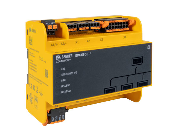
COMTRAXX® EDGE500IP
Combines data from compatible Bender and third-party devices in a shared web view and provides connections to supervisory systems.
Check interface, parameter setting and visualisation capabilities against the selected software function modules; the device does not replace a measuring sensor.Explore the model and documents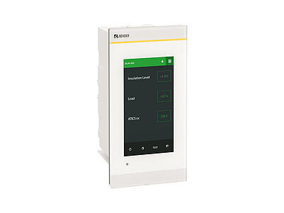
COMTRAXX® CP305
Presents compatible messages from MEDICS, EDS and RCMS systems to users with plain text and colour status indications.
Select the source device, message text and panel connection together; the panel does not itself measure insulation resistance.Explore the model and documents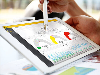
POWERSCOUT®
Evaluates connected measuring and monitoring device data through web dashboards, long-term analysis and automatic reports.
Data transfer requires the compatible device and gateway combination specified by the manufacturer.Explore the model and documents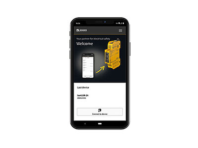
Bender Connect App
Simplifies parameter settings, configuration backups and parameter documentation on supported devices.
Reading energised devices and setting parameters on de-energised devices are separate functions; this is not a gateway for continuous central data collection.Explore the model and documentsEach product is assessed according to the interfaces and functions specified by the manufacturer. ADEO Teknik is Bender's distributor in Türkiye, supporting product selection and access to technical documents. Images and product images belong to Bender.
Bender sources for these models
Bender technical explanations
This English summary is based on the Bender technical sources listed below.
- Bender — COMTRAXX EDGE500IP ↗
- Bender — COMTRAXX CP305 ↗
- Bender — POWERSCOUT ↗
- Bender — Bender Connect App ↗
- Bender — System components ↗
- Bender — Series AT-Display panels ↗
- Bender — COMTRAXX MK2430 ↗
Sources checked: 2026-10-20. Diagrams belong to Bender; explanations were summarised by ADEO Teknik and are presented here in English.