

A brief look at the operating principle
Managing energy flow, detecting residual current and authorising the user are different tasks at a Mode 3 AC charging point. The controller, power module, compatible sensor and user interface form a system together; each component's role must be assessed separately.
Roles of RDC-DD, RDC-M and the external RCD
RDC-DD (Residual Direct Current Detecting Device) refers to DC residual current detection in Mode 3 AC charging under IEC 62955. RDC-M is the monitoring module integrated into the charging equipment. For RDC104-4, the compatible measuring current transformer, evaluation module and switching element are considered together; the module alone is not presented as a complete protective device. An external Type A RCD remains required.
- Detection and evaluation: A compatible measuring current transformer supplies the residual current signal; the RDC-M or electronics in the charge controller evaluates it.
- Switching: The threshold-exceedance signal is passed to a suitable driver and switching element that disconnects the load. Signal outputs such as Switch1/Switch2 are not presented as power contacts.
- Protection: An external Type A RCD is additionally required in the RDC104-4 solution and CC613 application described here. A sensor or control module alone does not provide that protective function.
From connection to energy transfer: CP/PP and state sequence
In Mode 3 AC charging, the controller manages communication with the vehicle and the charging station hardware. Control Pilot (CP) forms part of control communication between the vehicle and station. In suitable socket-based architectures, the Proximity Pilot (PP) connection helps identify the connected charging cable. These pilot lines serve a different purpose from the power conductors carrying load current. A controller signalling the permitted charging current does not mean the complete system operates at identical power under every condition.
The general sequence is to detect connection, complete any required authorisation, assess vehicle and station conditions, enable power switching when appropriate, and monitor charging. The state changes when the vehicle waits, charging finishes or a fault occurs. User authorisation, vehicle readiness and electrical permissions must be assessed together; presenting a card alone is not sufficient to start energy transfer. The detailed state sequence depends on the software and station configuration.
The controller board and IPM power module are different components
Controllers such as CC613 bring together communication with the vehicle, meter, supervisory system and user interfaces. Dynamic load management helps allocate the available power budget between charging points and adapt the limit signalled to the vehicle. Check the exact model and software scope for communication interfaces, modem, OCPP and ISO 15118 functions. Do not assume that every variant in a series has identical connections and protocols. In a station with two charging points, for example, controller communication roles and each point's power components are defined together. Load management decisions based on meter data differ from verifying the user's identity.
ICC1314 is a controller board used with a separate IPM power module; the controller board does not contain all the power module hardware. In the IPM1300 example, the power relay, DC supply also used by the controller, current transformer and monitoring components such as temperature sensing are located in the power module. The controller evaluates the transformer signal, and the control system manages the main power relay. Selecting the controller board alone therefore does not select the complete power and monitoring chain.
DC residual current detection forms part of the protection arrangement
In AC charging, the residual current sensor evaluates the balance of currents in the monitored circuit. A suitable sensor and electronic evaluator can detect DC fault current. This current measurement differs from the IMD measurement that monitors insulation resistance at a DC fast-charging output. The controller uses measurement results and other fault information to manage the charging state.
The CC613 manufacturer page explicitly requires a suitable external measuring current transformer and an external Type A RCD for DC residual current evaluation. In the IPM1300, the measuring current transformer forms part of the power module and is assessed together with ICC1314. The presence of a sensor or relay does not mean all protective duties are fulfilled independently. Measurement, evaluation, switching and protection components must be assessed using the selected product combination's documents.
RFID, HMI and displays: exchanging information with the user
The RFID module sends card information to the controller. Depending on the station configuration, user authorisation can use supervisory system records or a local whitelist in the controller. The reader alone is neither a charging controller nor a residual current protective device. In a suitable system, HMI modules and displays provide user interaction and display charging and operating states.
Ready, awaiting authorisation, charging, suspended and fault indications on an LED or display describe different stages. Display formats vary with model, software and configuration and cannot be generalised from one panel to another. Compatibility between the controller board, IPM, sensor, RFID/HMI and display must be verified in product documents. As Bender's distributor in Türkiye, ADEO Teknik supports application-appropriate model and variant selection, technical product information and access to manufacturer documents.
Bender components by task in an AC charging system
The controller, power module and user interface perform different tasks. The examples below show two different control architectures and a separate authorisation component; all parts are not presented as one common combination.
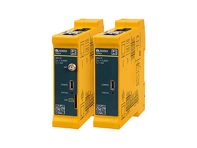
CC613 Charge Controller
Combines CP/PP communication, dynamic load management and management of station components. DC residual current evaluation is completed with a suitable external measuring current transformer.
An external Type A RCD remains required; modem, interface and software functions must be checked for the selected variant.Explore the model and documents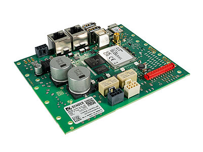
ICC1314
Performs control and communication tasks in an AC charging system. Supply, power switching and relevant measuring components are provided by a compatible IPM power module.
Do not assume ICC1314 contains an IPM1300 power module; verify controller board and module compatibility for the exact variant.Explore the model and documents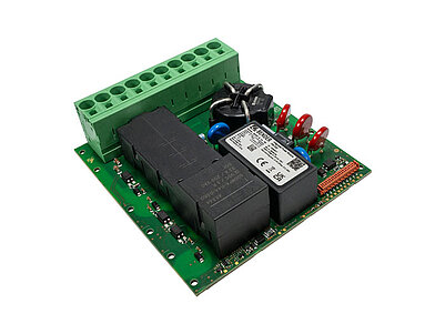
IPM1300
A separate power module used with a compatible ICC1314. Contains a power relay, DC supply and DC residual current measuring current transformer; measurement and switching operate together with the controller.
Neither a standalone charging controller nor a replacement for the complete protection arrangement. Use the manufacturer's ICC1314 variant compatibility information.Explore the model and documents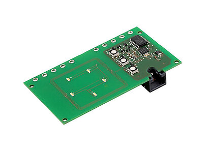
RFID105 / RFID114 / RFID117
Sends card information to a compatible controller. Depending on configuration, authorisation is evaluated using a supervisory system or local whitelist.
Does not measure or switch power. Select the RFID submodel, status LEDs and controller connection separately.Explore the model and documentsCC613 and ICC1314–IPM represent alternative architectures; the examples are not used as one combined device set. As Bender's distributor in Türkiye, ADEO Teknik supports suitable model, accessory and current technical document selection. Product images belong to Bender.
Bender sources for these models
Bender technical explanations
This English summary is based on the Bender technical sources listed below.
- Bender — CC613: Mode 3 control, CP/PP, load management and sensor requirements ↗
- Bender — ICC1314: separate controller board and IPM architecture ↗
- Bender — IPM1300: power relay, supply and current transformer roles ↗
- Bender — RFID105/114/117: user authorisation and status indication ↗
- Bender — Charging, waiting and fault states in ICC controllers ↗
- Bender — IEC 62955: RDC-DD, RDC-M and the switching element ↗
- Bender — RDC104-4: Mode 3 RDC-M module and external Type A RCD ↗
Sources checked: 2026-10-22. Diagrams belong to Bender; Turkish explanations summarised by ADEO Teknik.