

A brief look at the operating principle
An IMD measures insulation resistance between live conductors and earth to detect deterioration early. Its measuring method must suit the system's AC/DC configuration, power electronics and system leakage capacitance.
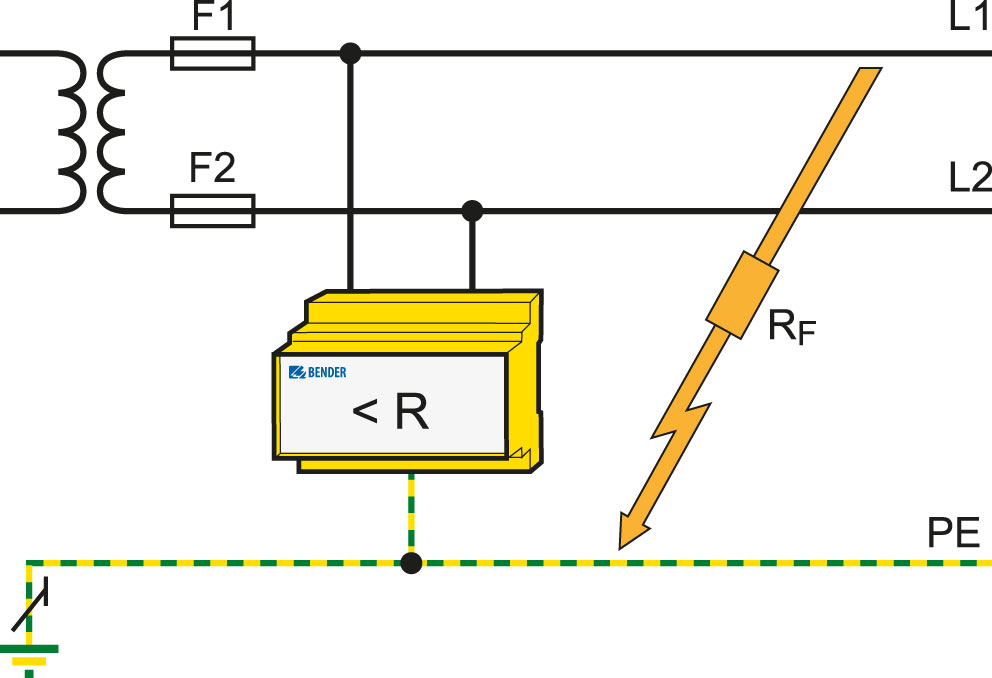
A measuring signal makes the insulation condition visible
An insulation monitoring device applies a measuring signal between the live conductors of an IT system and earth. It evaluates information from the measuring circuit formed when insulation deteriorates and calculates insulation resistance. The displayed Riso value represents the overall condition of the electrically interconnected system. This measurement does more than observe the load's operating current; an IMD and a residual current monitor therefore serve different purposes.
Why must symmetrical faults be considered separately?
An asymmetrical fault occurs when one conductor's insulation to earth deteriorates more than the others. A fault is symmetrical when the conductors' insulation deteriorates to approximately the same degree. An approach that evaluates only voltage displacement relative to earth may miss symmetrical deterioration. A suitable IMD measuring principle covers both cases. Particularly in DC circuits and control systems, this distinction shows why a device cannot be selected by its name alone.
System characteristics influence the measuring method
Rectifiers, frequency converters and system capacitance to earth can affect measuring behaviour. Bender uses various measuring methods for different system conditions; AMP and AMP Plus capabilities must be checked for the relevant model. Alarm thresholds are set according to system requirements. On models with two thresholds, prewarning and main alarm can support separate operating steps. Measurement and alarms inform the maintenance team; identifying the faulty outgoing circuit may additionally require a compatible fault location arrangement. Correct system and PE connections are also fundamental to reliable monitoring.
Explore IMD measurement through products
The insulation monitoring principle must be understood alongside device measuring conditions and alarm outputs. Explore a compact IMD and a main-circuit device offering different measuring profiles.
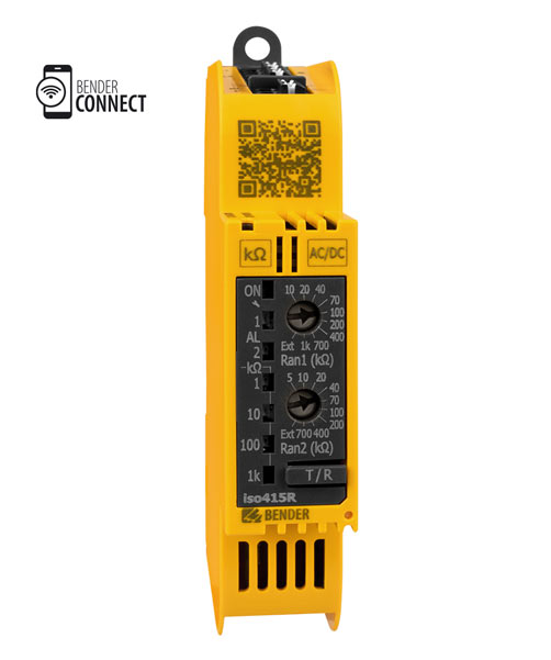
ISOMETER® iso415R
Monitors insulation resistance in unearthed AC and DC systems, indicating status through AL1/AL2 indicators and an alarm relay.
The suitability assessment includes system voltage, the 25 µF Ce limit and the condition that main circuits contain no VFDs.Explore the model and documents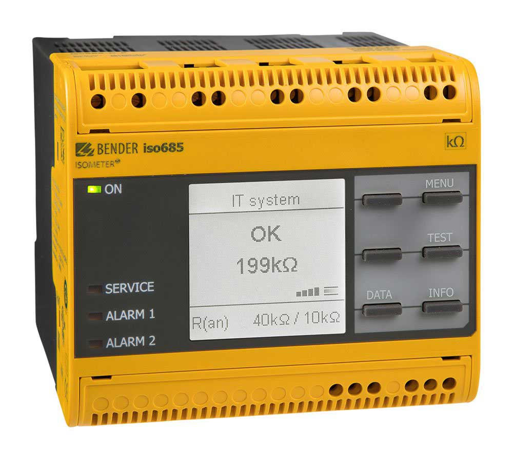
ISOMETER® iso685…
Uses AMP Plus and other profile-dependent measuring methods in IT main circuits. isoGraph shows changes in insulation resistance over time.
The two alarm thresholds are set according to system conditions; locating the faulty feeder requires a separate fault location arrangement.Explore the model and documentsDo not assume the models share the same measuring method, voltage range or Ce capability. Product images belong to Bender.
Bender sources for these models
Bender technical explanations
This English summary is based on the Bender technical sources listed below.
Sources checked: 2026-10-19. Diagrams belong to Bender; explanations were summarised by ADEO Teknik and are presented here in English.