

A brief look at the operating principle
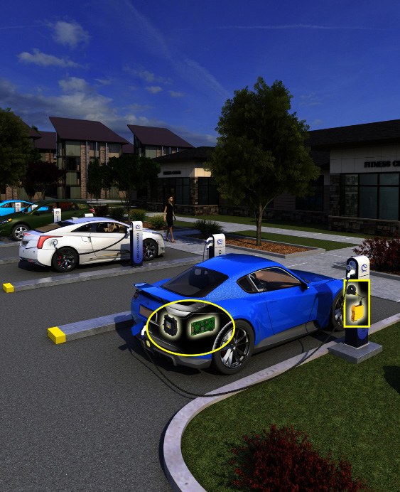
A DC charging station's output and a vehicle's high-voltage system require separate device selection. The monitored electrical boundary, charging scenario and control interface determine the suitable insulation monitoring solution.
First define the DC circuit being monitored
In DC charging, insulation monitoring tracks the insulation resistance between the live conductors of the unearthed DC circuit and earth. Deteriorating insulation produces an alarm for the charging control system to evaluate. However, the station's DC output, charging cable and vehicle high-voltage system do not form the same electrical boundary in every operating state. Contactor positions and galvanic separation change which section is included in the measurement. Rather than considering voltage range alone, the precharging, connection and energy transfer states must be defined together.
This is different from AC residual current monitoring
Residual current sensors in AC charging assess the sum of currents through the monitored conductors and are used with suitable protection and switching arrangements. A DC-sensitive sensor still performs this current measurement. An IMD, by contrast, determines the insulation resistance of the unearthed DC system using an active measuring method. An AC-side residual current sensor therefore does not automatically provide the required insulation monitoring at the DC output. Nor does an IMD alone fulfil every protection and disconnection function in the installation.
DC in RDC-DD refers to the DC residual current component detected during Mode 3 AC charging. This differs from the IMD function that monitors insulation resistance at a DC fast-charging output.
isoCHA425HV and iso175 serve different locations
The isoCHA425HV is specified for CCS/CHAdeMO DC charging stations with a suitable AGH420-1 or AGH421-1 coupling device. Measuring profiles and alarm settings are adapted to the application; information can be sent to the charging controller via interfaces such as Modbus RTU over RS-485. The iso175 is intended for unearthed high-voltage vehicle drive systems; depending on the variant, it communicates via Bender CAN or SAE J1939 and can measure before the HV system is energised. These models are not general-purpose substitutes for one another. System voltage, system leakage capacitance, measuring profile, control sequence and interface must be considered together. As Bender's distributor in Türkiye, ADEO Teknik supports the selection of suitable models and technical sources.
Different IMD solutions for charging stations and vehicles
The DC charging station output and vehicle high-voltage system are different monitoring boundaries. These two Bender models help compare where the device is used and which control interface it requires.
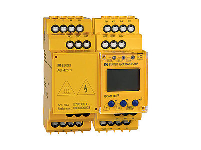
ISOMETER® isoCHA425HV with AGH420-1/AGH421-1
Monitors insulation resistance in CCS/CHAdeMO DC fast-charging stations with an AGH420-1 or AGH421-1 coupling device. The Modbus RTU interface supports transfer of measurement and alarm information to the charging controller.
Verify the voltage range, coupling device, charging profile and circuit section included in the measurement against the relevant variant's documents.Explore the model and documents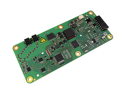
ISOMETER® iso175
Developed for unearthed drive systems in hybrid, fuel-cell and electric vehicles. Its active measuring method can measure before the HV system is energised; it communicates information to the vehicle controller over CAN.
Intended for on-board applications; it is not a general substitute for isoCHA425HV in DC charging stations.Explore the model and documentsStation and vehicle devices are not interchangeable; define the measuring boundary, contactor positions and control sequence together. Product images belong to Bender.
Bender technical explanations
This English summary is based on the Bender technical sources listed below.
- Bender — Insulation monitoring in DC charging infrastructure ↗
- Bender — Residual current monitoring in AC charging infrastructure ↗
- Bender — isoCHA425HV datasheet, pp. 2–3 ↗
- Bender — iso175 datasheet, pp. 2–3 ↗
- Bender — iso175 vehicle applications and interfaces ↗
Sources checked: 2026-10-19. Diagrams belong to Bender; explanations were summarised by ADEO Teknik and are presented here in English.