

A brief look at the operating principle
In an HRG system, the neutral grounding resistor limits earth fault current. Since an open resistor or a change in its resistance affects system behaviour, both the NGR and fault current are monitored.
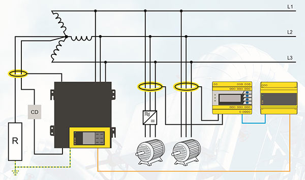
What does the neutral grounding resistor do?
In high resistance grounding (HRG), the supply neutral is connected to earth through a high-resistance neutral grounding resistor. The neutral grounding resistor, or NGR, limits the current during an earth fault. Some industrial installations use this approach to reduce damage and unplanned downtime. Current limitation depends on the entire system configuration as well as the resistance value. A single resistor or fault current value therefore cannot be prescribed for every installation.
NGR and NGRM: the resistor and its monitoring device
NGR (Neutral Grounding Resistor) is the resistor connected between neutral and earth. NGRM (Neutral Grounding Resistor Monitor) is the device that monitors its condition and the associated current and voltage. The neutral grounding resistance monitored by an NGRM differs from the system insulation resistance monitored by an IMD and from earth electrode resistance.
- HRG (High Resistance Grounding): earthing through a high resistance. NGRM500 and NGRM700 are intended for this application scope.
- LRG (Low Resistance Grounding): earthing through a low resistance. NGRM550 and NGRM750 are intended for this application scope.
- The NGR limits earth fault current; the NGRM monitors the resistor and related electrical quantities. Alarm and tripping are assessed together with suitable external circuit-breaking and control equipment.
Why is resistor integrity monitored separately?
An interruption in the NGR path can impair the expected fault detection behaviour. Excessively low resistance also changes the current-limiting function. Bender NGRM700 monitors NGR resistance, current through this path and neutral-to-earth voltage. With a suitable arrangement, resistance monitoring can continue while the installation is de-energised. Transferring measured values to a monitoring system, alongside event history and alarms, supports maintenance assessment.
Plan alarm, fault location and tripping together
Depending on system design, NGRM700 can be connected to an earth fault alarm or tripping arrangement; RCMS solutions can support separate assessment of outgoing circuits. Overall earthing information and investigation of the faulty feeder then complement one another. Since healthy phases may rise in voltage relative to earth after the first earth fault, the risk of a second fault must not be ignored. HRG is not presented as a solution for limiting phase-to-phase arc energy. Particularly in mobile equipment and mining, monitoring, disconnection and continuity requirements depend on the application and local rules; continued operation after the first fault must not be assumed under all conditions.
NGR monitoring devices and coupling component for HRG
NGRM700 and NGRM500 monitor NGR resistance and related electrical quantities in high-resistance-earthed HRG systems. CD1000 is the complementary coupling device used within a suitable voltage range.
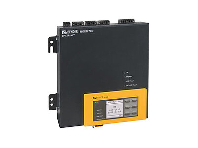
LINETRAXX® NGRM700
Monitors neutral grounding resistor condition, current and voltage in an HRG system. A detachable HMI, Ethernet and web server support local display and access from supervisory monitoring systems.
Intended for HRG applications; do not assume the same application scope as NGRM750, which is specified for LRG.Explore the model and documents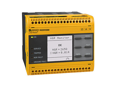
LINETRAXX® NGRM500
Evaluates neutral resistor condition, current through it and neutral-to-earth voltage. Active and passive measuring methods support NGR resistance monitoring even when the installation is de-energised.
The manufacturer specifies NGRM500 for HRG systems only; alarm/tripping settings depend on installation conditions.Explore the model and documents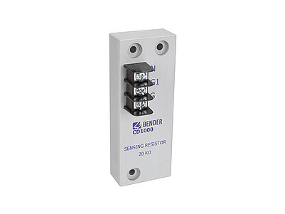
CD1000
A coupling device used to connect an NGR monitor in an HRG system. Bender lists CD1000 as a compatible accessory for both NGRM700 and NGRM500.
Not a standalone monitoring device. Check voltage, operating altitude and connection conditions alongside the compatible NGR monitor's documents.Explore the model and documentsNGR monitors are alternative model options; the coupling device and current sensor are selected according to system voltage, current and wiring arrangement. Product images belong to Bender.
Bender technical explanations
This English summary is based on the Bender technical sources listed below.
- Bender — Electrical safety for high resistance grounded systems ↗
- Bender — LINETRAXX NGRM700: monitored quantities and functions ↗
- Bender — Neutral Grounding Resistance (NGR) Monitoring ↗
- Bender — NGRM500/NGRM550: HRG/LRG datasheet ↗
- Bender — NGRM700/NGRM750: HRG/LRG datasheet ↗
Sources checked: 2026-10-22. Diagrams belong to Bender; Turkish explanations summarised by ADEO Teknik.