

A brief look at the operating principle
Voltage and load current are evaluated together to calculate power; its accumulation over time provides energy information. A power quality device, energy meter and residual current monitor do not perform the same measuring task.
From voltage and current to power and energy information
Voltage alone does not explain an electrical circuit's consumption. The measuring device evaluates voltage together with the circuit's load current. The relationship between phases and current behaviour relative to voltage are used to obtain quantities such as active, reactive and apparent power. Active power describes the current rate of energy transfer, while active energy is the accumulated amount over a period. Instantaneous power and the energy total on a meter therefore answer different questions.
In three-phase measurement, each current input must be matched to the correct phase voltage. The current transformer ratio and connection direction are also considered. The measurement chain includes voltage connections, the current sensor, device settings and communication information. A displayed value alone does not prove that the connections are correct under every condition.
The difference between power quality analysis and consumption recording
PEM353 provides harmonic and total harmonic distortion information alongside voltage, current, power and energy. This allows electrical conditions and consumption to be examined together. Threshold monitoring and recording capabilities depend on the variant; features such as neutral current measurement through a separate input are not identical across all PEM353 versions.
ALD1, ALE3 and AWD3 energy meter options emphasise consumption recording for energy management, while also providing voltage, current, power and cos φ data. Data can be transferred using Modbus RTU. Providing these values does not mean an energy meter also offers the PEM353's harmonic analysis capabilities. Single-phase, three-phase and current-transformer connection options are selected from the relevant model table. Certification and intended use must also be checked for the exact ordering variant.
How does CTB/KBR load current measurement differ?
For load current measurement, CTB/KBR converts the current in the monitored phase conductor into a secondary current suited to the measuring device input. CTB is an example of a closed-window transformer and KBR of a split-core transformer. Primary/secondary ratio, measuring range and required accuracy are selected together with the device. A family offering 1 A and 5 A secondary options does not mean each option suits every PEM input. The published PEM353 variant table specifies 5 A phase current inputs.
This differs from residual current measurement. In RCM, all live conductors of the monitored circuit, including the neutral where present, pass through a shared measuring window; PE does not. The evaluated quantity is the difference in the sum of currents, rather than the load current of one phase. A load current transformer therefore cannot be selected in place of an RCM sensor merely because they look physically similar.
From the measurement objective to a suitable Bender solution
First define the information required: a meter for total consumption, a suitable PEM solution for power and harmonic behaviour, or a compatible RCM measurement chain for residual current monitoring. Collecting values over communication does not change these devices' measuring tasks. As Bender's distributor in Türkiye, ADEO Teknik supports product selection and access to current technical documents.
Bender models for power, energy and load current
Match the measured quantity to the device function. These three product groups illustrate the different tasks of analysers, energy meters and load current transformers.
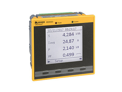
LINETRAXX® PEM353
Records and displays voltage, current, power and energy, with THD and harmonics up to the 31st order included in its measurements.
The listed PEM353 phase current inputs are 5 A. A separate neutral current input is provided on the PEM353-N variant.Explore the model and documents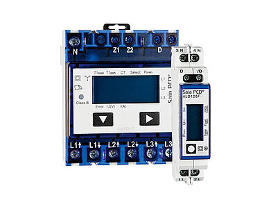
ALD1 / ALE3 / AWD3
Alongside energy recording, ALD1, ALE3 and AWD3 options provide current, voltage, power and cos φ information, with Modbus RTU data transfer.
Check the connection type and exact ordering variant. Energy measurement must not be equated with the PEM353's harmonic analysis capabilities.Explore the model and documents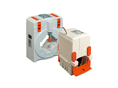
CTB / KBR measuring current transformers
Closed-window CTB and split-core KBR options transfer load current to a suitable device input; the family includes 1 A and 5 A secondary options.
Current ratio and secondary input compatibility must be selected together. CTB/KBR serve a different purpose from RCM residual current sensors.Explore the model and documentsPower quality, energy consumption and residual current are different measurement objectives. Verify the exact model, current transformer and wiring arrangement together. Product images belong to Bender.
Bender sources for these models
Bender technical explanations
This English summary is based on the Bender technical sources listed below.
- Bender — LINETRAXX® PEM353: measurements and variants ↗
- Bender — Energy meter: energy meter options ↗
- Bender — Measuring current transformers: CTB and KBR ↗
- Bender — How does residual current monitoring work? ↗
Sources checked: 2026-10-20. Diagrams belong to Bender; explanations were summarised by ADEO Teknik and are presented here in English.